WiFi Transmitter Circuit – Build a Wireless Network! Transmitter circuit design
Alright, let's talk a little bit about wireless power, shall we? It's a fascinating field, really, conjuring up images of a truly cable-free future. We're not quite there yet, but the fundamental principles have been understood for quite some time, and the advancements being made are truly impressive. The key, of course, lies in understanding how to efficiently transmit and receive energy without a physical connection. It involves intricate circuit designs, careful component selection, and a dash of electromagnetic wizardry. I've been digging around and came across a couple of interesting diagrams that highlight the core concepts.
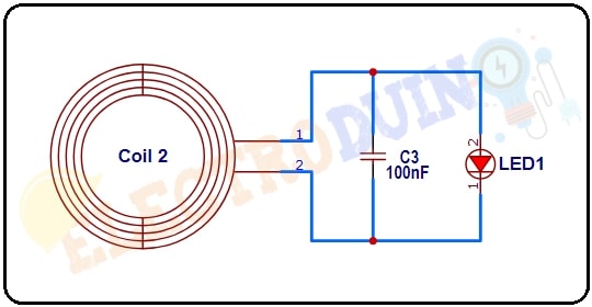
Wireless Power Transmitter Circuit Diagram

This first diagram showcases a pretty standard approach to wireless power transmission. You'll notice the oscillator circuit, typically employing transistors or ICs, responsible for generating a high-frequency signal. This signal then feeds into a resonant inductor, which acts as the transmitting antenna. The crucial part here is the resonance. By carefully selecting the inductance and capacitance values, we can create a circuit that efficiently oscillates at a specific frequency. When another resonant inductor (the receiving antenna) is brought within proximity, the electromagnetic fields couple, allowing energy to be transferred from one circuit to the other. The efficiency of this transfer is highly dependent on the frequency, the distance between the coils, and the alignment of the coils. Think about it like two finely tuned tuning forks – when one is struck, the other will resonate in sympathy. The same principle applies here, but with electromagnetic fields instead of sound waves.
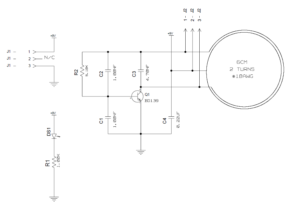
Transmitter Circuit Design

Now, this second diagram provides a more granular view of a potential transmitter circuit. What’s neat here is seeing the detail afforded to managing impedance matching. Impedance matching is vital for maximizing power transfer. If the impedance of the transmitter doesn't match the impedance of the antenna or the receiving circuit, a significant portion of the power will be reflected back, resulting in decreased efficiency. This diagram shows us that careful component selection around the matching networks is key to minimizing those losses. You'll also notice various filtering components, intended to suppress unwanted harmonics or noise that could interfere with the transmission. This is particularly important in regulated environments where electromagnetic interference (EMI) needs to be kept within acceptable limits. Designing these circuits is not a walk in the park, of course. It requires a solid understanding of RF principles, circuit analysis, and the characteristics of the components being used. Software simulation tools are often employed to fine-tune the design and predict its performance before building a physical prototype.
Ultimately, wireless power is more than just a convenience; it opens up new possibilities in various applications. Think about charging electric vehicles without cables, powering medical implants wirelessly, or enabling fully automated factories with robots moving freely without being tethered to power outlets. The ongoing research and development in this field are constantly pushing the boundaries of what's possible, and I'm excited to see what the future holds. It's a world of resonators, electromagnetic fields, and hopefully, soon enough, a lot fewer tangled wires.
If you are looking for Wireless Power Transmitter Circuit Diagram - Circuit Diagram you've came to the right web. We have 25 Images about Wireless Power Transmitter Circuit Diagram - Circuit Diagram like Wifi Transmitter And Receiver Circuit Diagram, Wireless Power Transmitter Circuit Diagram and also Wireless Power Transmitter Circuit Diagram. Read more:
Wireless Power Transmitter Circuit Diagram - Circuit Diagram
www.circuitdiagram.co Wireless Electricity Transmission Circuit Diagram - Circuit Diagram
 www.circuitdiagram.co
 Wireless Power Transmission Project Circuit Diagram - Circuit Diagram
 www.circuitdiagram.co
 Wifi Transmitter And Receiver Circuit Diagram
 www.circuitdiagram.co
 Free Download Program Wifi Transmitter And Receiver Circuit Diagram
 trustoutlet.weebly.com
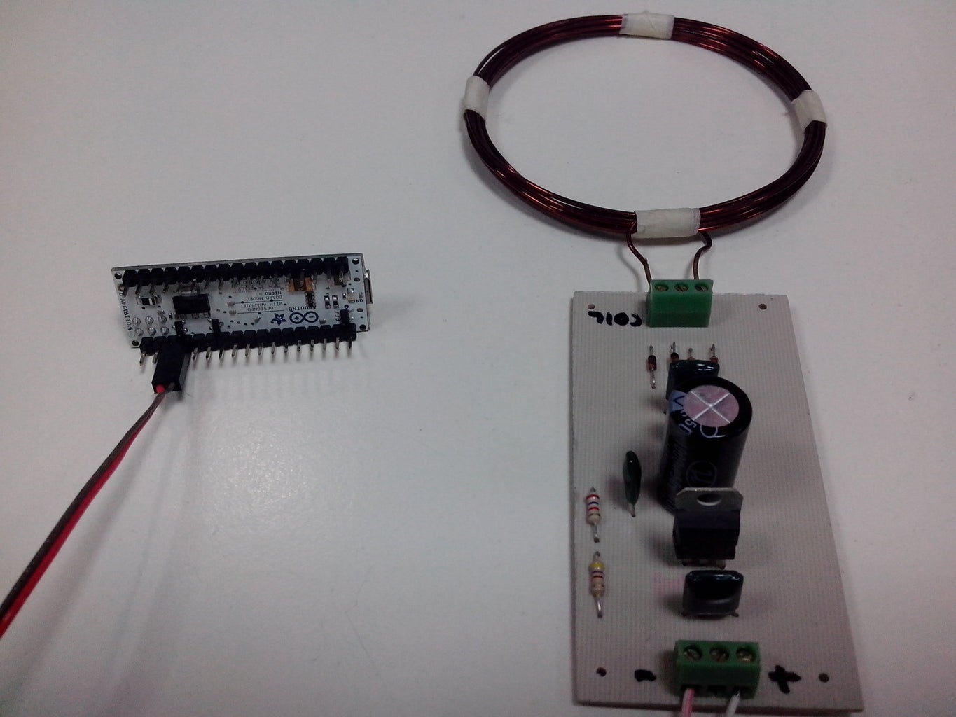
 Wireless Power Transmitter And Receiver : 6 Steps - Instructables
 www.instructables.com
 Wireless Power Transmitter Circuit Diagram
 www.circuitdiagram.co
 Fm Wireless Transmitter Circuit – Artofit
 www.artofit.org
 (PDF) Wireless Power Transmitter Circuit - DOKUMEN.TIPS
 dokumen.tips
 Wireless Communication Circuit Diagrams - Circuit Diagram
 www.circuitdiagram.co
 Wireless Power Transmitter And Receiver : 6 Steps - Instructables
 www.instructables.com
 Wireless Power Transmitter And Receiver | Trybotics
 trybotics.com
 transmitter
Transmitter Circuit Design. | Download Scientific Diagram
 www.researchgate.net
 Transmitter Circuit Design | Download Scientific Diagram
 www.researchgate.net
 Transmitter Circuit Design | Download Scientific Diagram
www.researchgate.net Transmitter Circuit Design | Download Scientific Diagram
Wireless Power Transmitter And Receiver Circuit
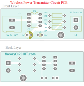 theorycircuit.com
 Wireless Transmission Circuit | Download Scientific Diagram
 www.researchgate.net
 Simple Wireless Circuit Diagram - Circuit Diagram
 www.circuitdiagram.co
 Wifi Transmitter And Receiver | Download Scientific Diagram
Wireless Transmitter Circuit | Download Scientific Diagram
 www.researchgate.net
 Wireless Transmitter Circuit Diagram. | Download Scientific Diagram
 www.researchgate.net
 circuit transmitter
Wifi Receiver Circuit Diagram - Circuit Diagram
 www.circuitdiagram.co
 Wireless Power Transfer Transmitter Circuit Diagram - Circuit Diagram
 www.circuitdiagram.co
 Oscillator - How To Increase Power Of A Wireless Power Transmitter
 electronics.stackexchange.com
 circuit wireless power transmitter increase multisim simulation how stack
Wireless power transmitter and receiver : 6 steps. Simple wireless circuit diagram. Wireless transmission circuit